|
700 Feedback Head |
700 Feedback Head |
820 Vista Vision 1 |
820 Vista Vision 3 |
|
01 |
|
|
|
|
|
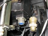
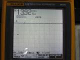
If voltage is bigger than 0.5VDC switch
off the machine anddisconnect the engrave head |
If voltage is bigger than 0.5VDC switch
off the machine anddisconnect the engrave head |
If voltage is bigger than 0.5VDC switch
off the machine anddisconnect the engrave head |
If voltage is bigger than 0.5VDC switch
off the machine anddisconnect the engrave head |
|
02 |
|
|
|
|
|
|
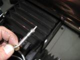
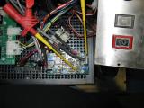
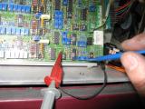
Remove kaman probe from engrave head |
|
|
|
|
Handle probe very carefully, it can break
extremely quick! |
|
|
|
|
Switch on the engraver. |
|
|
|
|
|
|
|
|
|
|
|
|
|
|
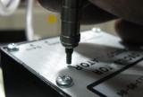
Touch slightly with kaman probe tip against
the aluminium surface of oscillator box. |
|
|
|
|
|
|
|
|
|
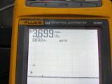
If probe tip is away from the aluminum the
voltage should be 13VDC |
|
|
|
|
If probe tip touches the aluminium (90°
angle) the voltage should be minus 2-4 VDC |
|
|
|
|
|
|
|
|
|
If the voltage is always around 13 VDC the
probe seems to be bad.
(Send to Weber Technics for replacement) |
|
|
|
|
|
|
|
|
|
If the voltage changes, but goes not to
minus 2-4 VDC the probe is not adjusted correctly.
(Send to Weber Technics for recalibration) |
|
|
|
|
|
|
|
|
|
Mount the tested or replaced kaman sensor
to the engrave head again.
Do not tighten the screw. |
|
|
|
|
Slide the kaman tip against the back of
the stylus arm, until the voltmeter shows less than +/- 0.02 VDC.
Tighten the screw. |
|
|
|
|
Use the feeler gauge to verify the space
between the back of the stylus arm and the kaman probe.
If you have no plastic feeler gauge use
an edge of a business card to slide between arm and probe. |
|
|
|
|
Basically the procedure is finnished. |
|
|
|
If the first five engraved cells looks not
even you can fine adjust the VG potentiometer at the velocity board. |
If the first five engraved cells looks not
even you can fine adjust the VG potentiometer at the P-Card. |
If the first five engraved cells looks not
even you can fine adjust the VG potentiometer at the velocity board. |
If the first five engraved cells looks not
even you can fine adjust the VG potentiometer at the P-Card. |
|
|
|
|
|
|
Attach the oszilloscope to 'POS' testpoint
on velocity board. |
Attach the oszilloscope to 'POS' testpoint
on the p-card. |
Attach the oszilloscope to 'POS' testpoint
on velocity board. |
Attach the oszilloscope to 'POS' testpoint
on the p-card. |
|
|
|
Engrave a horizontal stripe to the cylinder
with about 1-2 cm height |
|
|
|
|
Setup the oszilloscope |
|
|
|
|
|
|
|
|
|
Switch off the AC vibration |
|
|
|
|
|
|
|
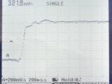
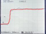
Find the front end response curfe |
Find the front end response curfe |
Find the front end response curfe |
Find the front end response curfe |
|
|
|
|
|
|
|
|
|
Adjust VG potentiometer |
|
|
|
|
|
|
|
|
|
Try to adjust 'VG' that the signal becomes
the red line. |
|
|
|
|
Switch on the AC vibration again |
|
|
|
|
Frontend (first five cells) should look
nice now. |
|
|
|
|
Frontend (first five cells) should look
nice now. |